Signal Physics From Orbit to Ground
The real specifications, power constraints, and transmission physics of modern satellite constellations — from Starlink LEO to GPS MEO.
Free-Space Path Loss vs. Distance
Signal attenuation across L, C, and Ku bands from 1 km to GEO orbit (35,786 km). Shows why satellite signals arrive extremely weak at ground level.
Modern Satellite Constellations
Starlink (SpaceX): Operating at ~540–570 km altitude in Low Earth Orbit (LEO), Starlink represents the largest satellite constellation ever deployed, with over 12,000 satellites operational as of 2026. Each V2 Mini satellite weighs ~800 kg and uses four phased-array antennas for beam-forming, enabling dynamic coverage of ground cells as small as 15 km in diameter. The satellites are deployed in 72 orbital planes at 53° inclination for global coverage.[16][22][50]
GPS (Global Positioning System): The constellation operates from Medium Earth Orbit (MEO) at ~20,200 km altitude across 31 operational satellites in 6 orbital planes. GPS signals are broadcast at L-band frequencies: L1 at 1.57542 GHz, L2 at 1.22760 GHz, and the modernized L5 at 1.17645 GHz. The total radiated power per satellite is approximately 50 W, resulting in an incredibly weak signal at ground level: approximately -130 dBm(10⁻¹⁶ watts, or ~0.01 femtowatts).
Amazon Kuiper: Amazon's planned constellation will deploy 3,236 satellites in three orbital shells (590 km, 610 km, and 630 km). The first prototype satellites (KuiperSat-1 and KuiperSat-2) were launched in October 2023. Full deployment is targeted for 2029, operating in Ka-band (17.7–20.2 GHz downlink, 27.5–30.0 GHz uplink).[57]
Telesat Lightspeed: A planned 298-satellite LEO constellation at ~1,000 km altitude, optimized for enterprise and government connectivity using advanced optical inter-satellite links and multi-beam Ka-band antennas.
Constellation Comparison
| System | Orbit | Altitude | Satellites | Freq Band | Latency |
|---|---|---|---|---|---|
| Starlink | LEO | 550 km | 12,000+ | Ku/Ka-band | ~25 ms |
| GPS | MEO | 20,200 km | 31 | L-band | ~135 ms |
| OneWeb | LEO | 1,200 km | 648 | Ku-band | ~50 ms |
| Iridium NEXT | LEO | 780 km | 66 (+9 spare) | L/Ka-band | ~30 ms |
| Amazon Kuiper | LEO | 590–630 km | 3,236 | Ka-band | ~30 ms |
| Telesat | LEO | ~1,000 km | 298 | Ka-band | ~40 ms |
Operating Frequencies & Signal Power
Starlink's primary downlink to user terminals uses the Ku-band (10.7–12.7 GHz), with uplinks at 14.0–14.5 GHz. Gateway links use Ka-band (17.8–20.2 GHz downlink, 27.5–30.0 GHz uplink) for higher throughput to ground stations. Research using the LOFAR radio telescope has detected unintended low-frequency emissions from Starlink satellites between 110–188 MHz, well below designated communication frequencies.[16][23][50]
Frequency Selection Trade-offs
The choice of operating frequency involves fundamental trade-offs. Higher frequencies provide more bandwidth (and thus data throughput) but suffer greater atmospheric attenuation, especially from rain (Ka-band can lose 10–20 dB in heavy rain). Lower frequencies penetrate weather better but offer less bandwidth and require larger antennas for equivalent gain. The relationship between frequency, antenna size, and beamwidth is governed by the diffraction limit: θ ≈ 70λ/D (degrees), where λ is wavelength and D is antenna diameter.
Satellite Frequency Bands
Power Specifications & EIRP
The maximum transmit EIRP for a Starlink satellite can reach 66.89 dBW(approximately 4.9 megawatts equivalent isotropic power). This enormous figure results from the antenna's high gain — the actual transmitter power is only about 40 watts, with the phased-array antenna focusing it into narrow, steerable beams. The relationship is:
EIRP (dBW) = P_tx (dBW) + G_antenna (dBi)
40 W = 16 dBW; antenna gain ≈ 51 dBi → EIRP ≈ 67 dBW
Power Budget Reality
A Starlink satellite generates approximately 10–20 kW from its two solar arrays. Of this, only a fraction is allocated to RF transmission — the rest powers the onboard computer, attitude control, thermal management, inter-satellite laser links, and battery charging for eclipse periods. The typical per-beam RF power is only 1–5 watts, with the total RF output across all beams limited to approximately 40 W.[22][25][50]
The power flux density (PFD) reaching Earth's surface is tightly regulated by the ITU to prevent interference with terrestrial systems. For Starlink, the documented PFD limit is −146 dBW/m² per 4 kHz. A standard Starlink user terminal ("Dishy") transmits with just 3.2 W EIRP, using a flat phased-array antenna with electronic beam steering.[25][50]
Critical Engineering Reality
Satellite communication systems are designed to deliver just enough power to be reliably detected by a purpose-built receiver — not to deliver energy. The signal at ground level is typically -120 to -150 dBm (∼10⁻¹⁵ to 10⁻¹⁸ watts), far below any biological effect threshold. Even the most powerful broadcasting satellite (GEO, ~200 W RF) delivers only ~10⁻¹² W/m² at ground level.
Modulation, Coding & Signal Processing
Modern satellite communication systems use sophisticated digital modulation and forward error correction (FEC) coding to maximize data throughput while operating at extremely low signal-to-noise ratios (SNR). Starlink employs adaptive coding and modulation (ACM) that dynamically adjusts modulation order and code rate based on real-time link quality.[22][58]
| Modulation | Bits/Symbol | Min SNR | Usage |
|---|---|---|---|
| QPSK | 2 | ~3 dB | Bad weather, low elevation |
| 8-PSK | 3 | ~7 dB | Normal conditions |
| 16-APSK | 4 | ~10 dB | Good conditions |
| 64-APSK | 6 | ~16 dB | Clear sky, high elevation |
The key insight is that these systems can reliably decode data from signals that are 10–15 dB below the noise floor thanks to sophisticated spread-spectrum techniques, LDPC/turbo coding, and large correlation gains from known spreading codes. GPS receivers, for example, can lock onto signals at -160 dBm (10⁻¹⁹ watts) using 1 ms C/A code correlation, achieving a processing gain of ~43 dB.[58]
Link Margin & System Design
Satellite link design follows a precise power budget accounting for every gain and loss in the signal path. The link margin is the difference between the received signal power and the minimum required for reliable demodulation (the receiver sensitivity). Typical design targets a margin of 3–6 dB to accommodate atmospheric fading, pointing errors, and component aging.[49][58]
Starlink Downlink Power Budget (Typical)
Note: This illustrates that the entire system is engineered with razor-thin margins. Every watt counts, and the received power is just barely above the noise floor — designed to transfer information, not energy.
The Inverse-Square Law
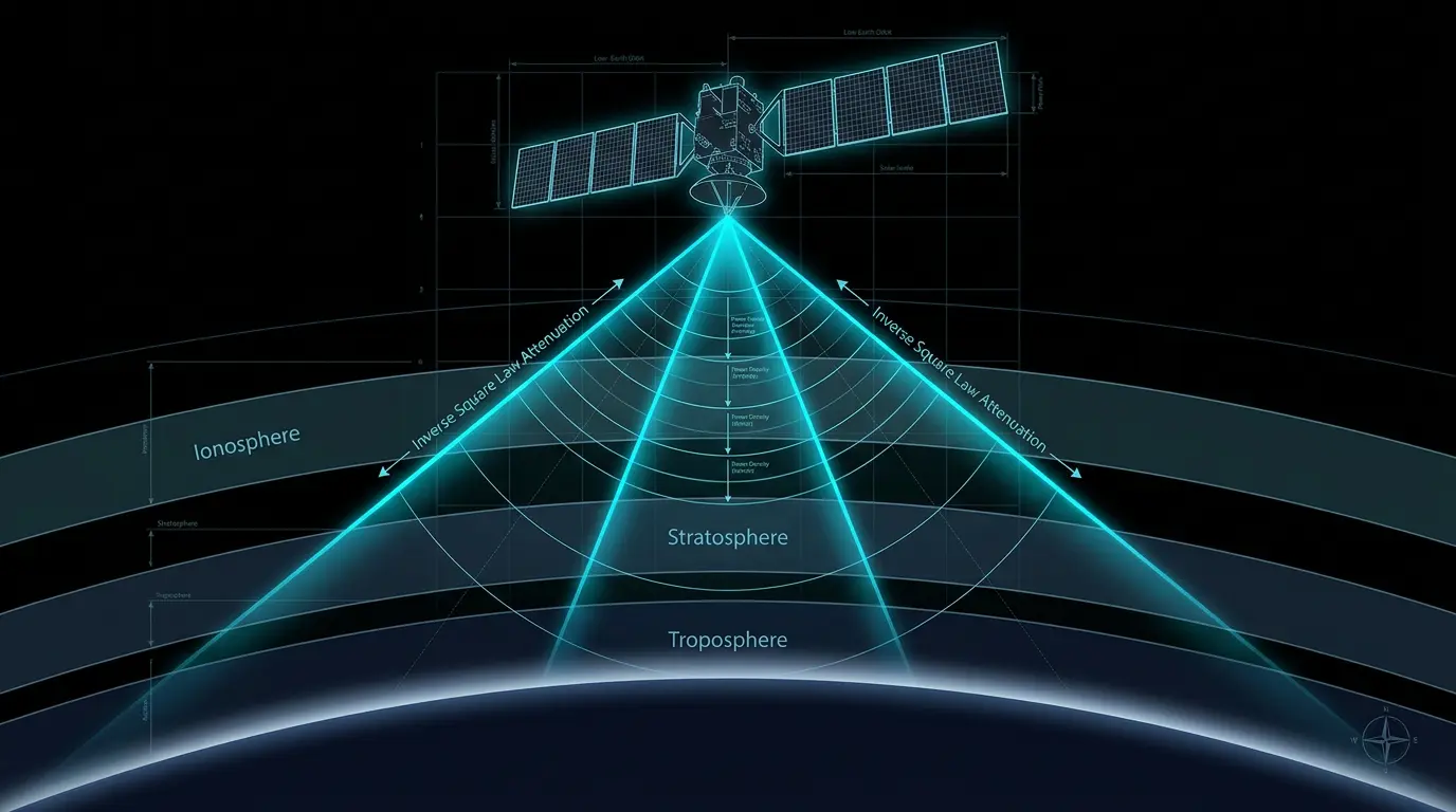
The fundamental obstacle to delivering energy from orbit is the inverse-square law: signal intensity decreases proportionally to the square of distance (Intensity ∝ 1/r²). The free-space path loss (FSPL) formula is:
FSPL(dB) = 20·log₁₀(d) + 20·log₁₀(f) + 20·log₁₀(4π/c)
where d = distance (m), f = frequency (Hz), c = speed of light
A 20 GHz signal traveling to GEO (~35,786 km) experiences approximately 210 dB of path loss — an astronomical reduction factor of 10²¹. Even at Starlink's closer 550 km altitude, the path loss at Ku-band exceeds 170 dB. To put this in perspective:[4][12]
170 dB loss means only 1 out of every 10,000,000,000,000,000,000 (10¹⁷) units of energy arrives at the destination.
40 watts transmitted from Starlink at 550 km produces approximately 10⁻¹⁰ W/m² at ground level without antenna gain on either end.
A 100-watt light bulb at the same distance would produce a power density roughly 10 billion times weaker than starlight.